Selected CAD development examples
Below are examples of the types of work we delivered.
Specific client files and confidential project details are only shared where permitted
This page presents selected examples of mechanical CAD work completed in SOLIDWORKS. The projects shown below illustrate different stages of development, including clean 3D modeling, internal geometry refinement, section analysis, design updates and production-oriented CAD preparation.
Some examples are shown in a simplified format to respect project confidentiality while still demonstrating the modeling approach, feature logic and level of detail.
Mechanical component development
A compact technical component developed with attention to internal geometry, feature logic and part structure. The selected views show both the final form and intermediate development steps used during refinement
Complex housing and geometry refinement
This example shows the development of a more complex technical part with multiple internal features, structural transitions and geometry checks. The process views help illustrate how the model was reviewed and refined in CAD
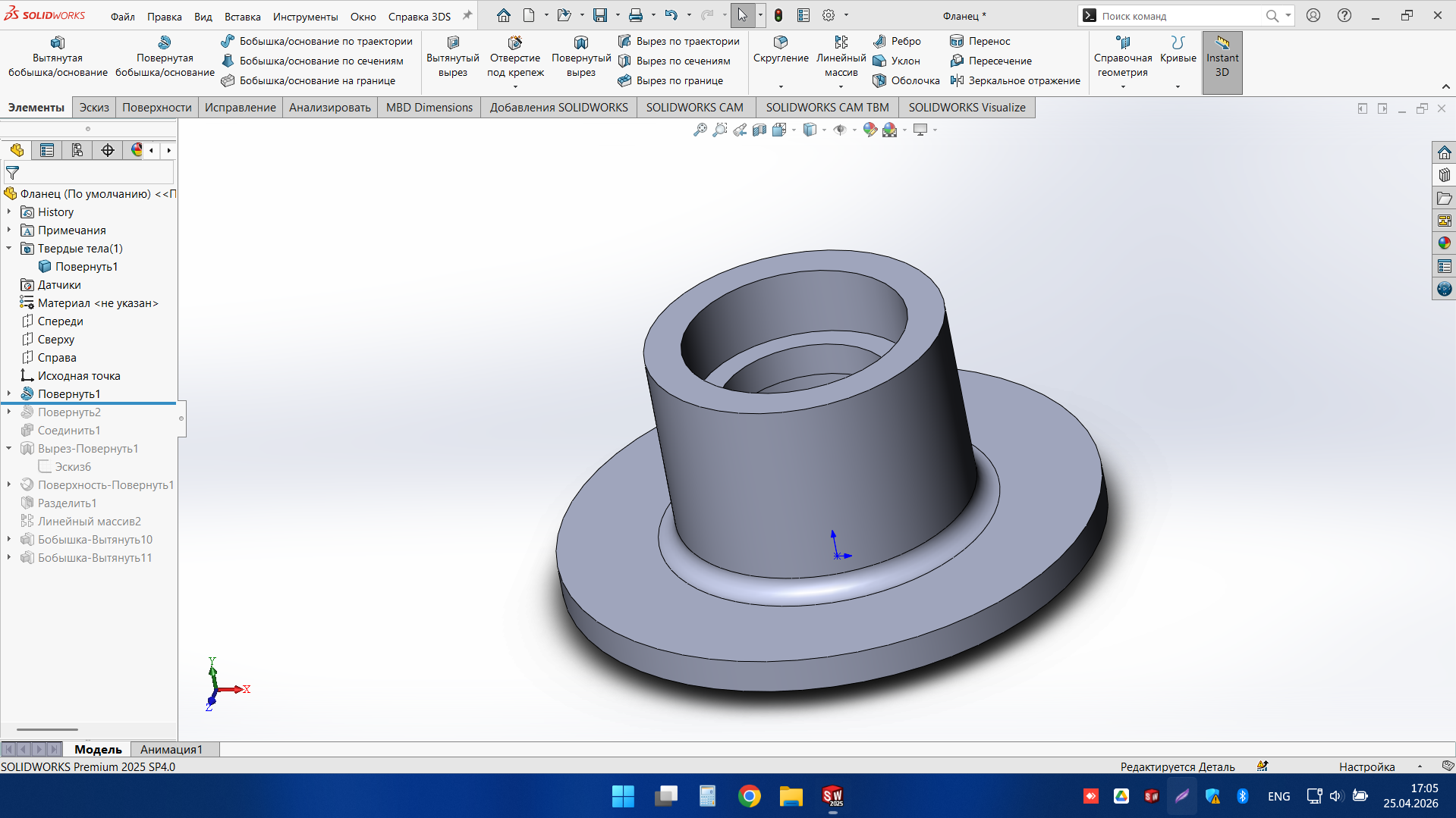
Circular component modeling
A circular mechanical part prepared as an editable CAD model for further integration and documentation. The available view highlights the overall geometry, mounting features and clean part definition
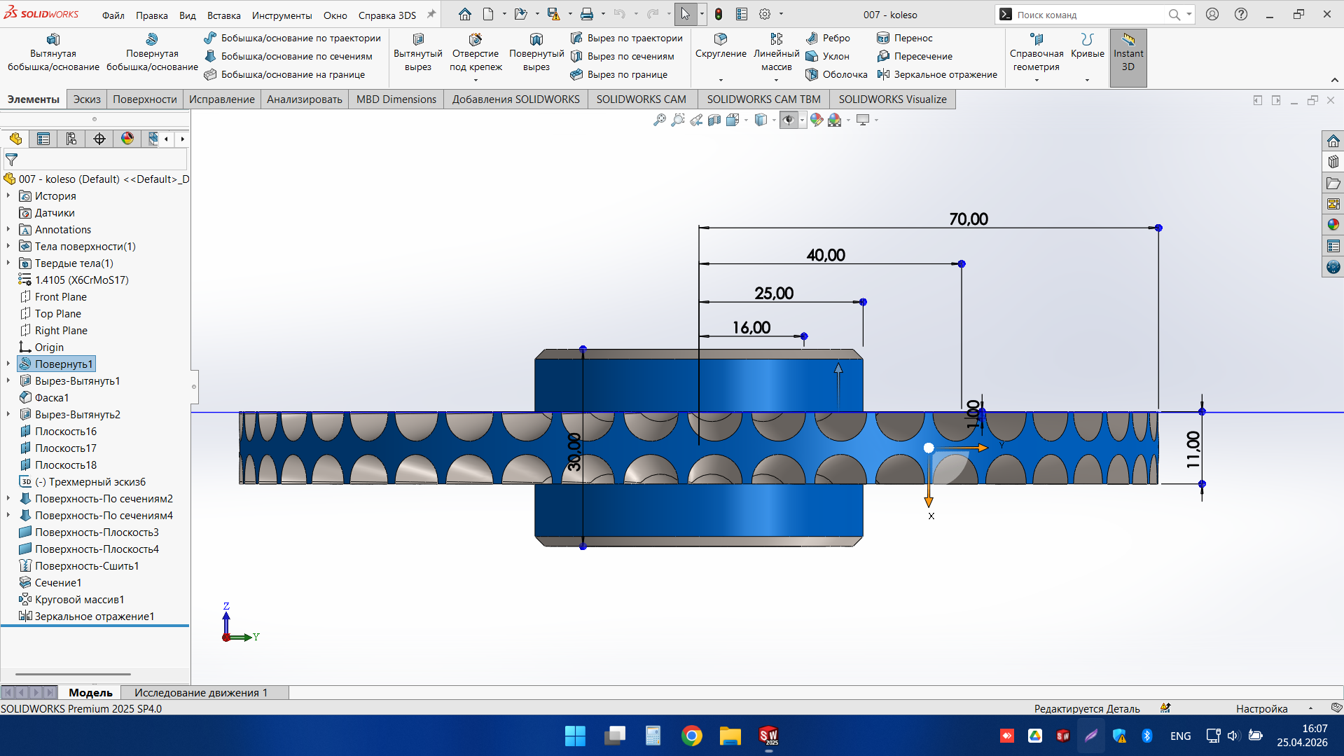
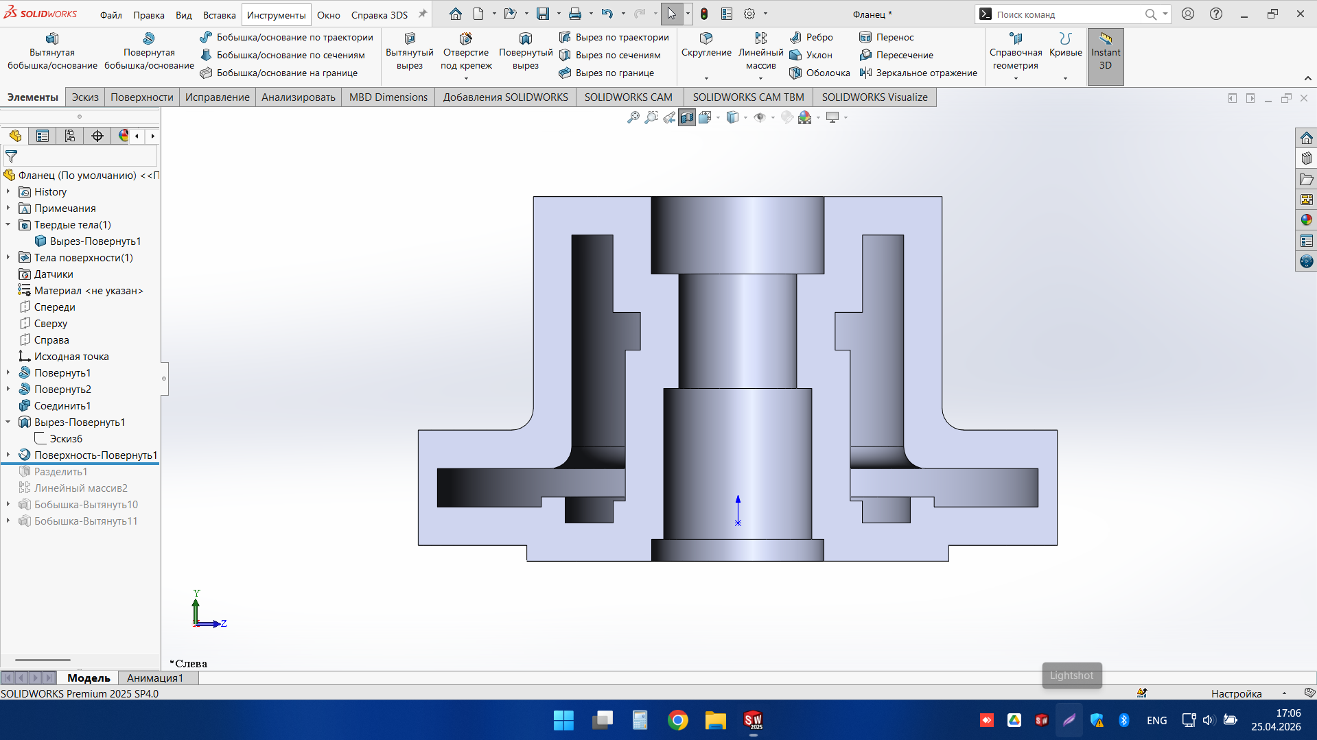
Rotational part with section-based control
This project demonstrates a rotational component modelled with repeated features and controlled proportions. The section view was used to verify the design logic and key dimensions during development
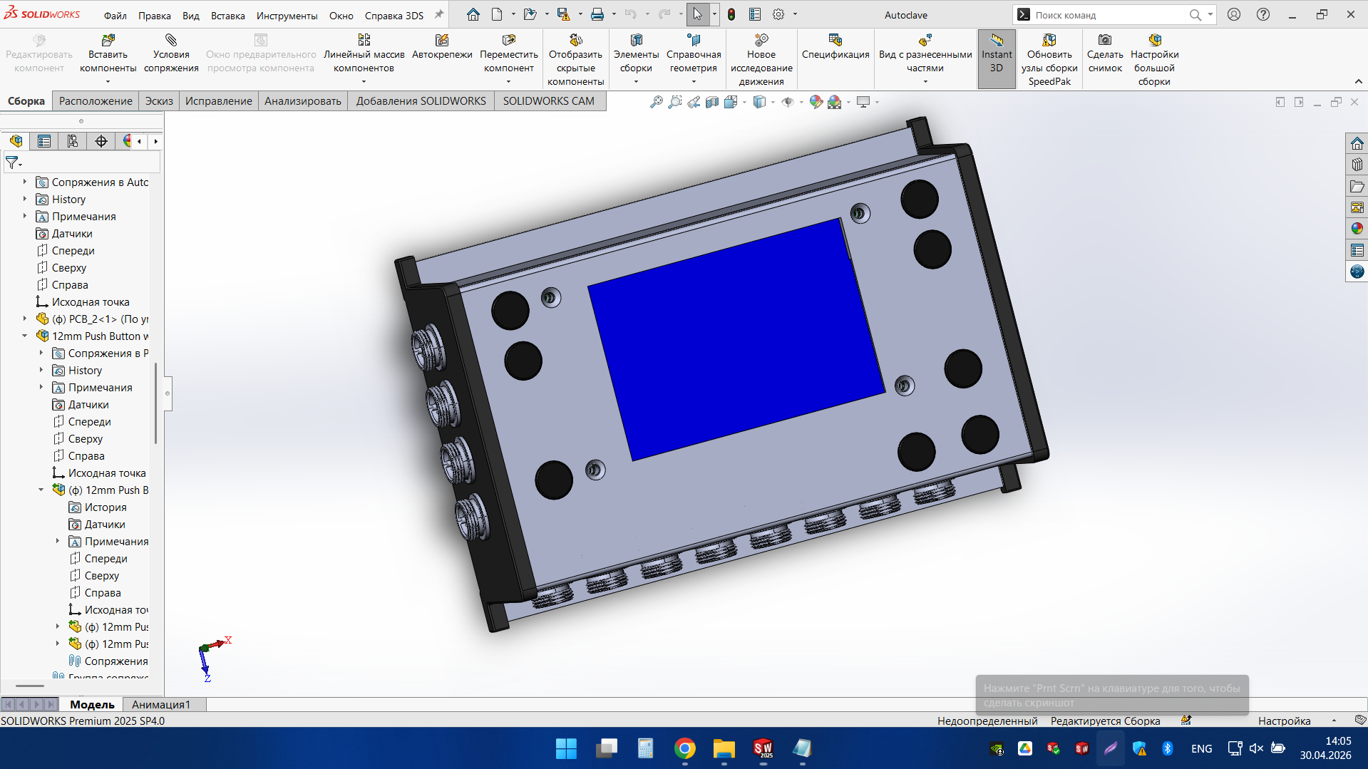
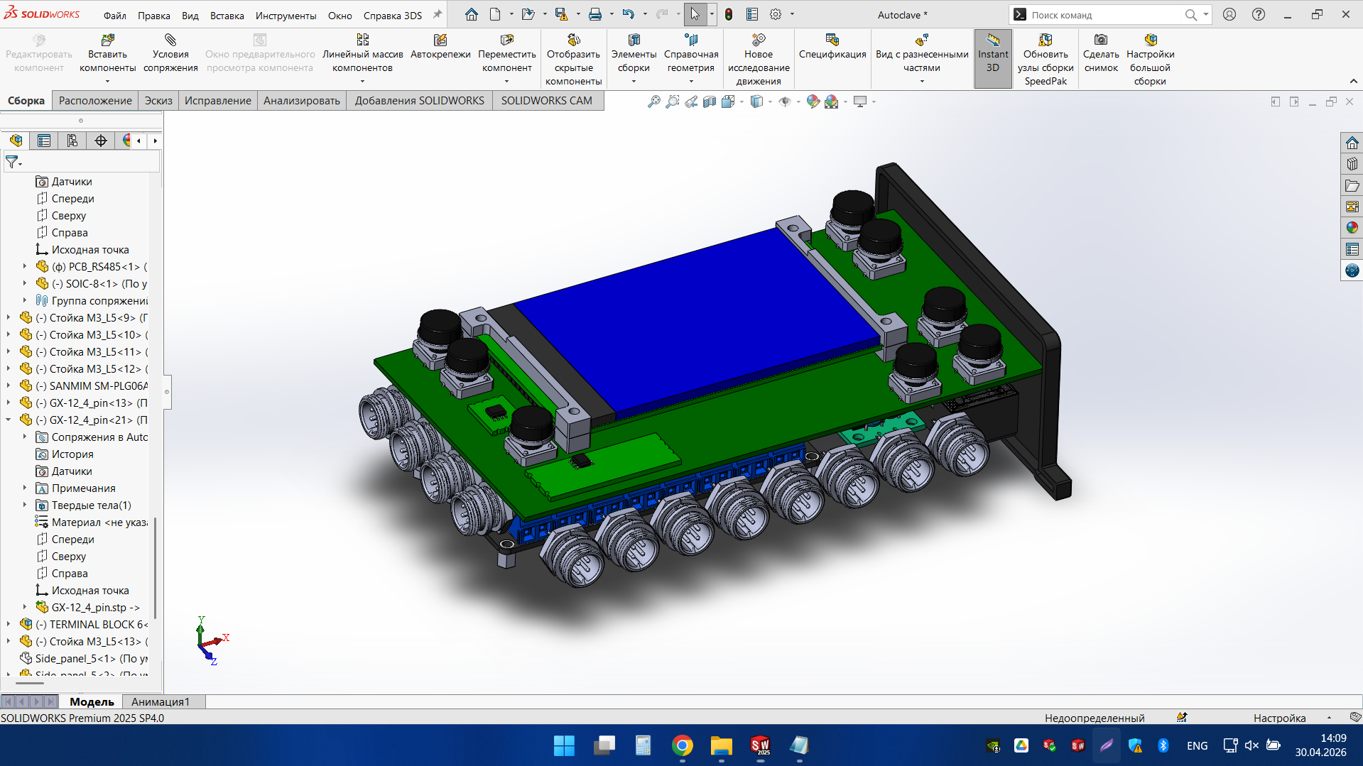
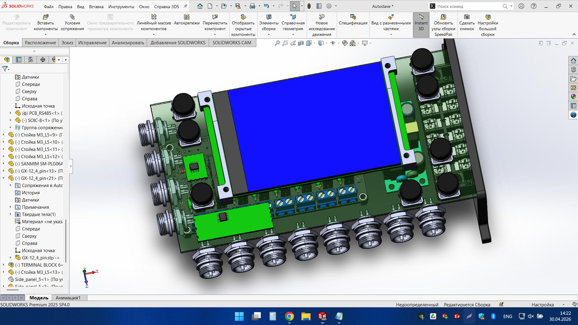
Autoclave control unit
The housing unit, electronic control board, circuit diagram and control program were developed based on the customer’s technical specifications
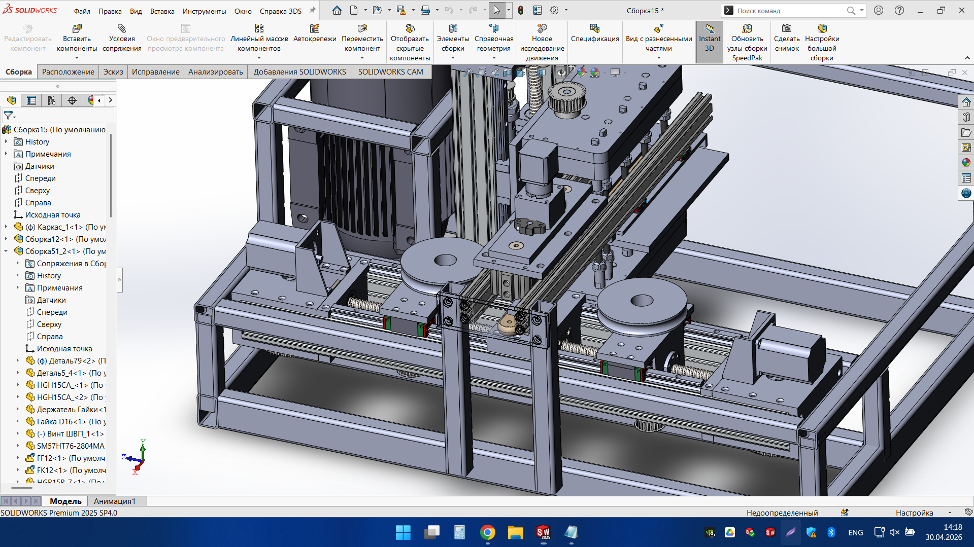
Fully automated machine
Automatic milling machine for making wooden handles for kitchen knives
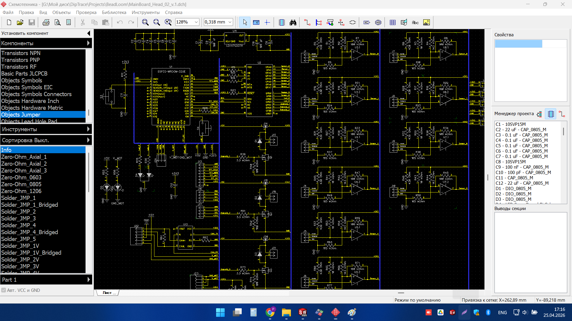
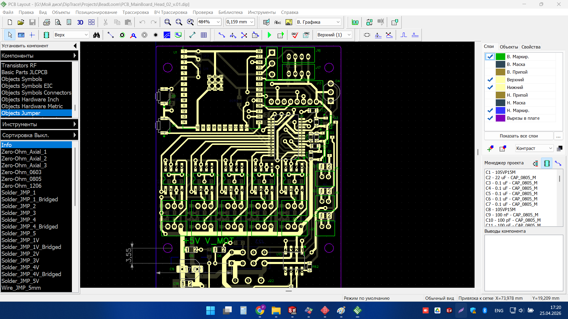
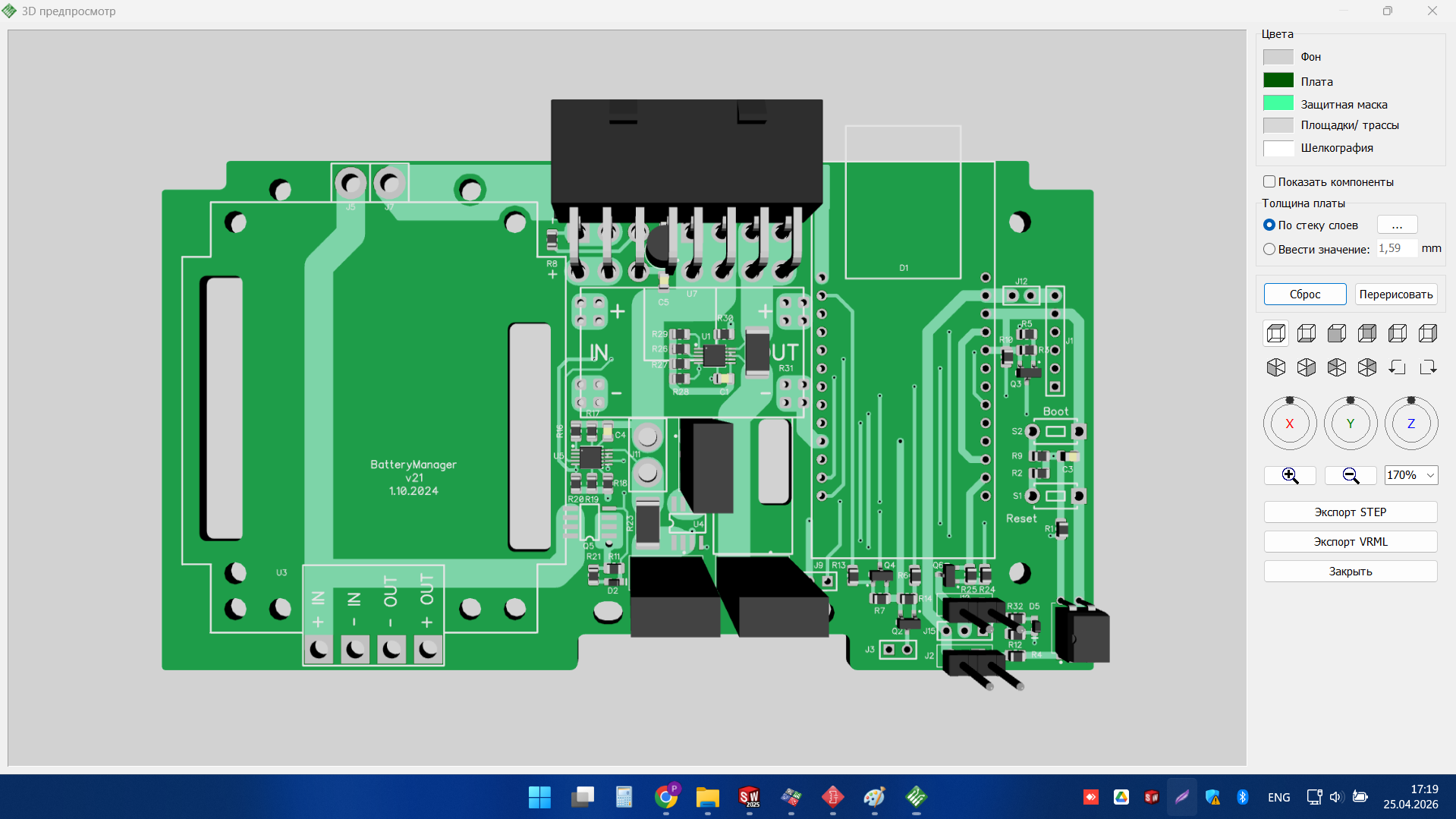
An electronic control board
Was developed from schematic design to PCB layout. The project included circuit structuring, component placement, routing and preparation of a manufacturable board design. The images show both the schematic stage and the 3D PCB view for reviewing the final arrangement and board geometry.
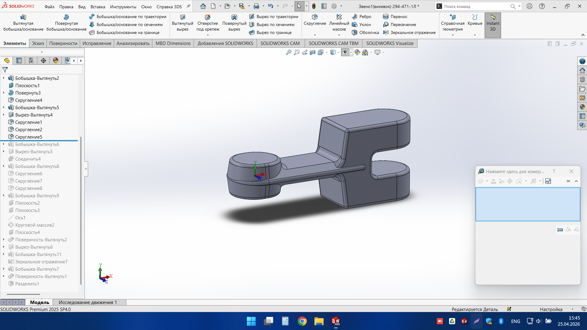
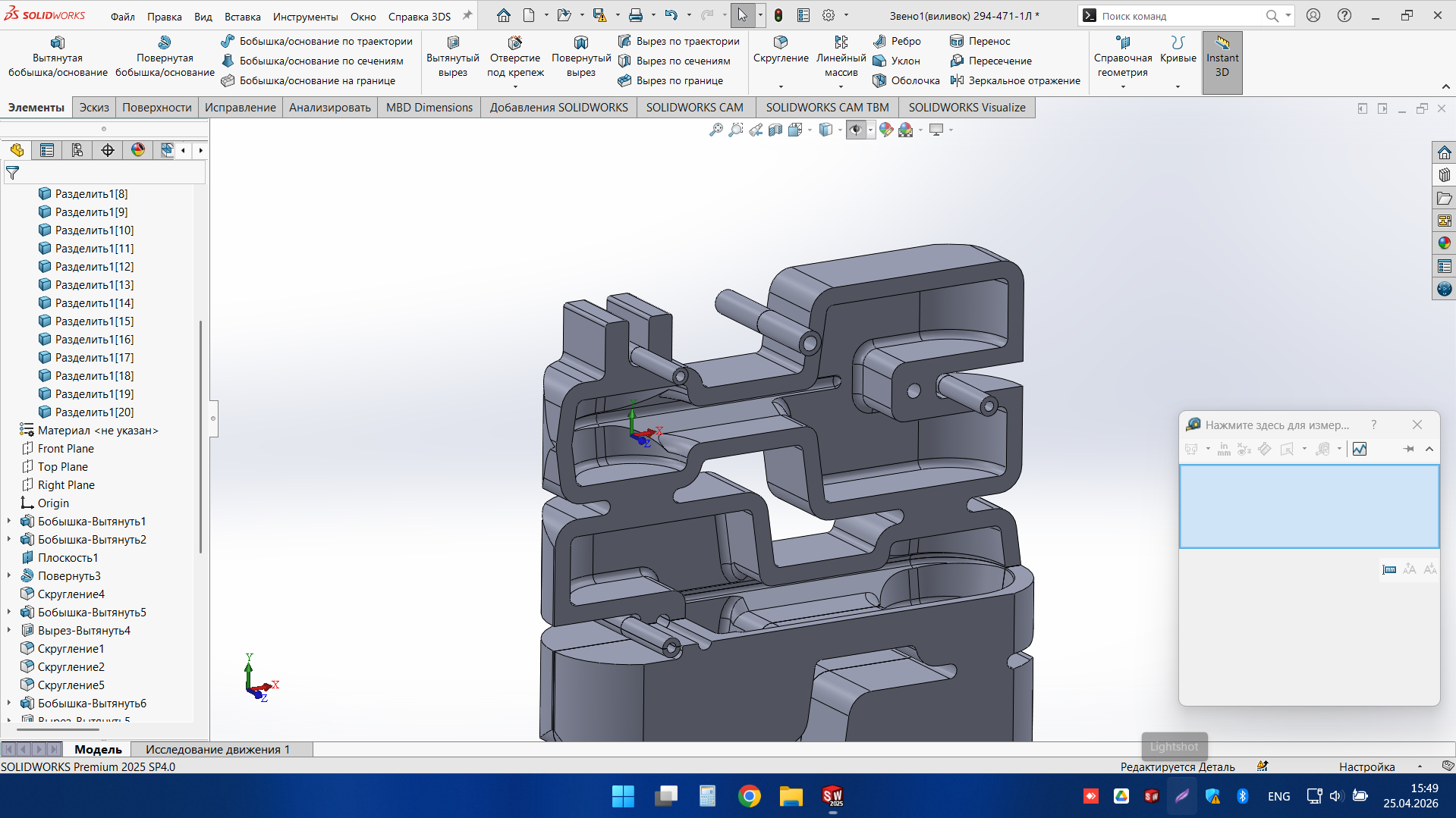
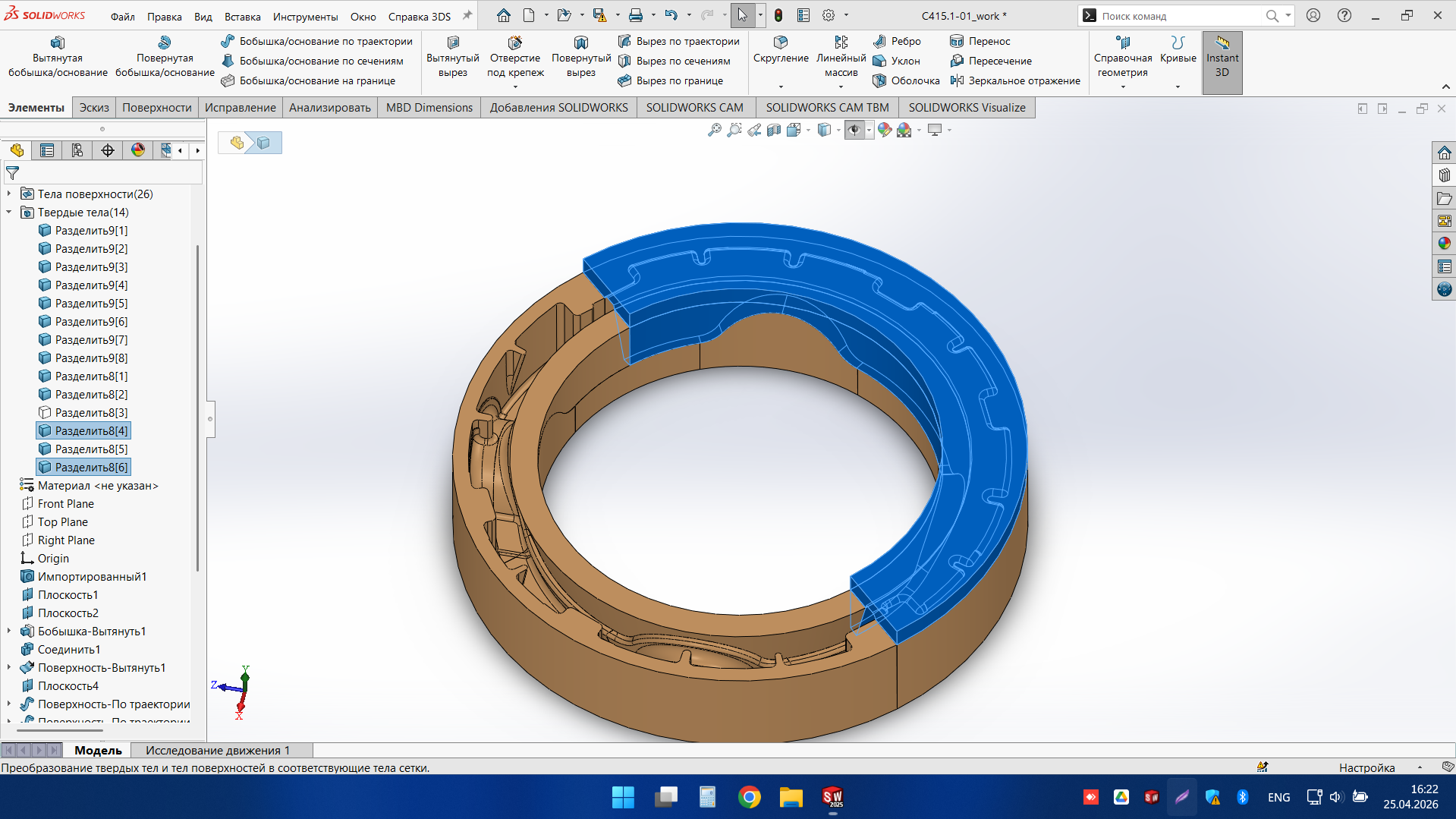
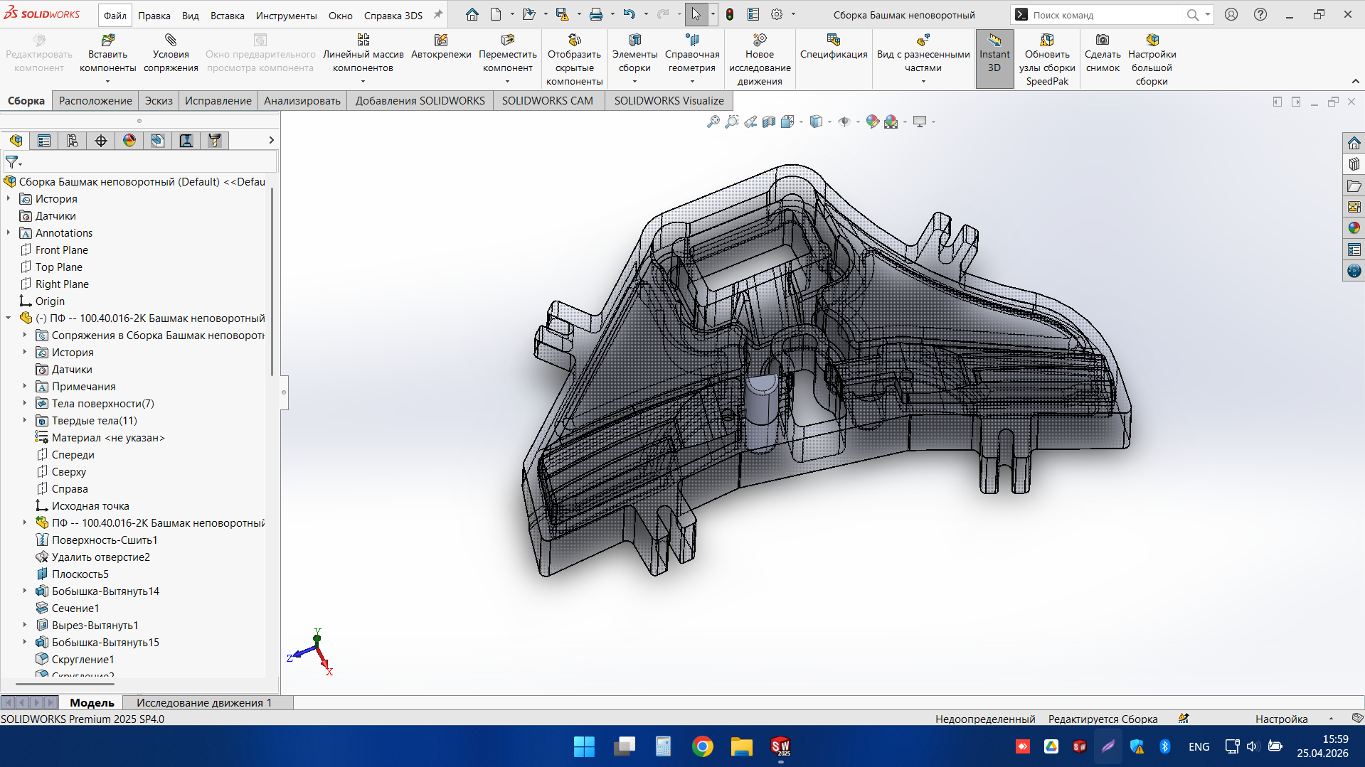
Precision mechanical component
This project demonstrates our approach to complex 3D CAD work for precision mechanical components. The part includes detailed internal geometry, functional interface areas, and multiple segmented sections that required careful modelling and refinement. The result is a clean, structured, and editable CAD model ready for further development and engineering coordination. It is a good example of the type of digital design support we provide for industrial and technical projects.
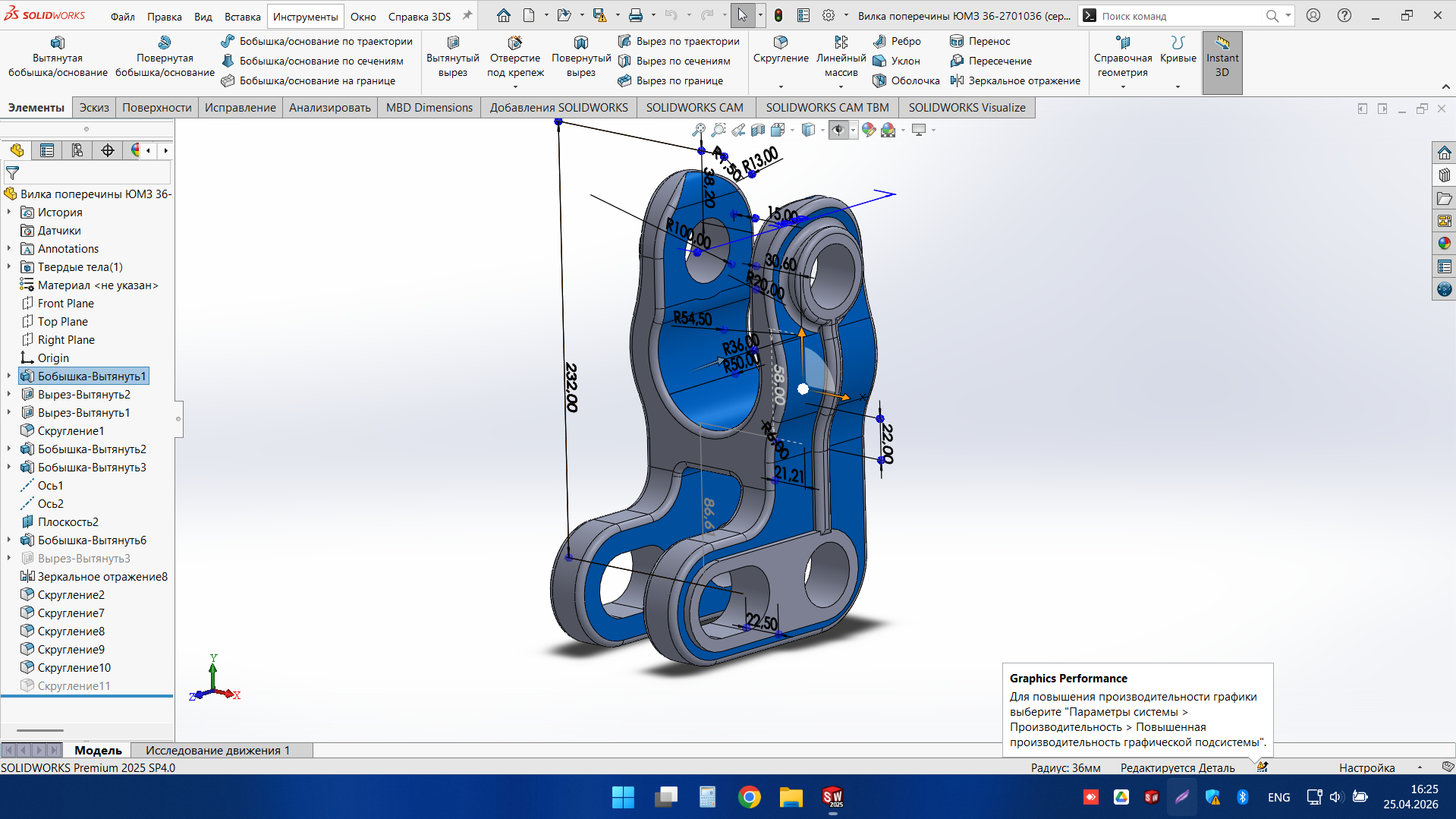
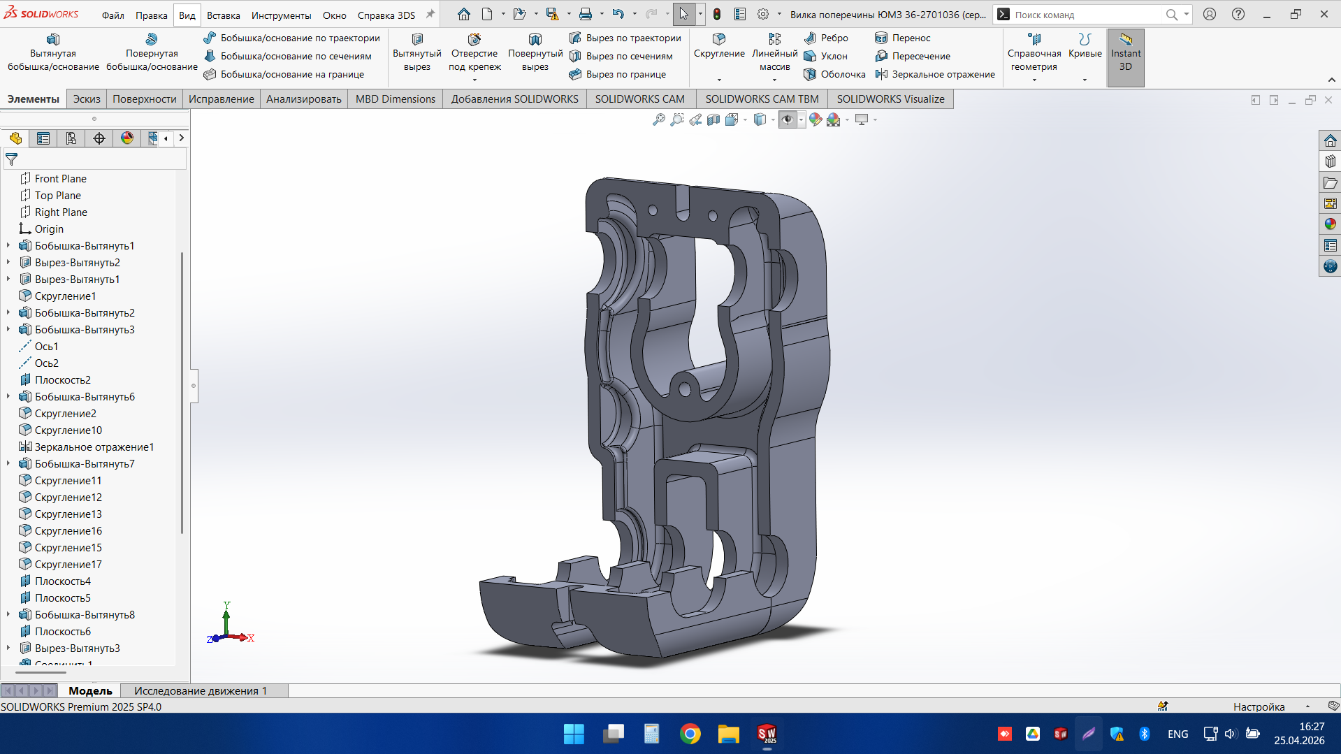
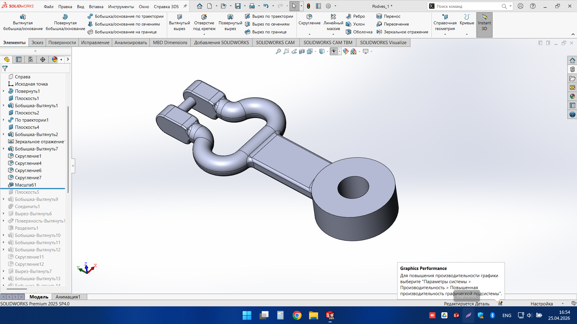
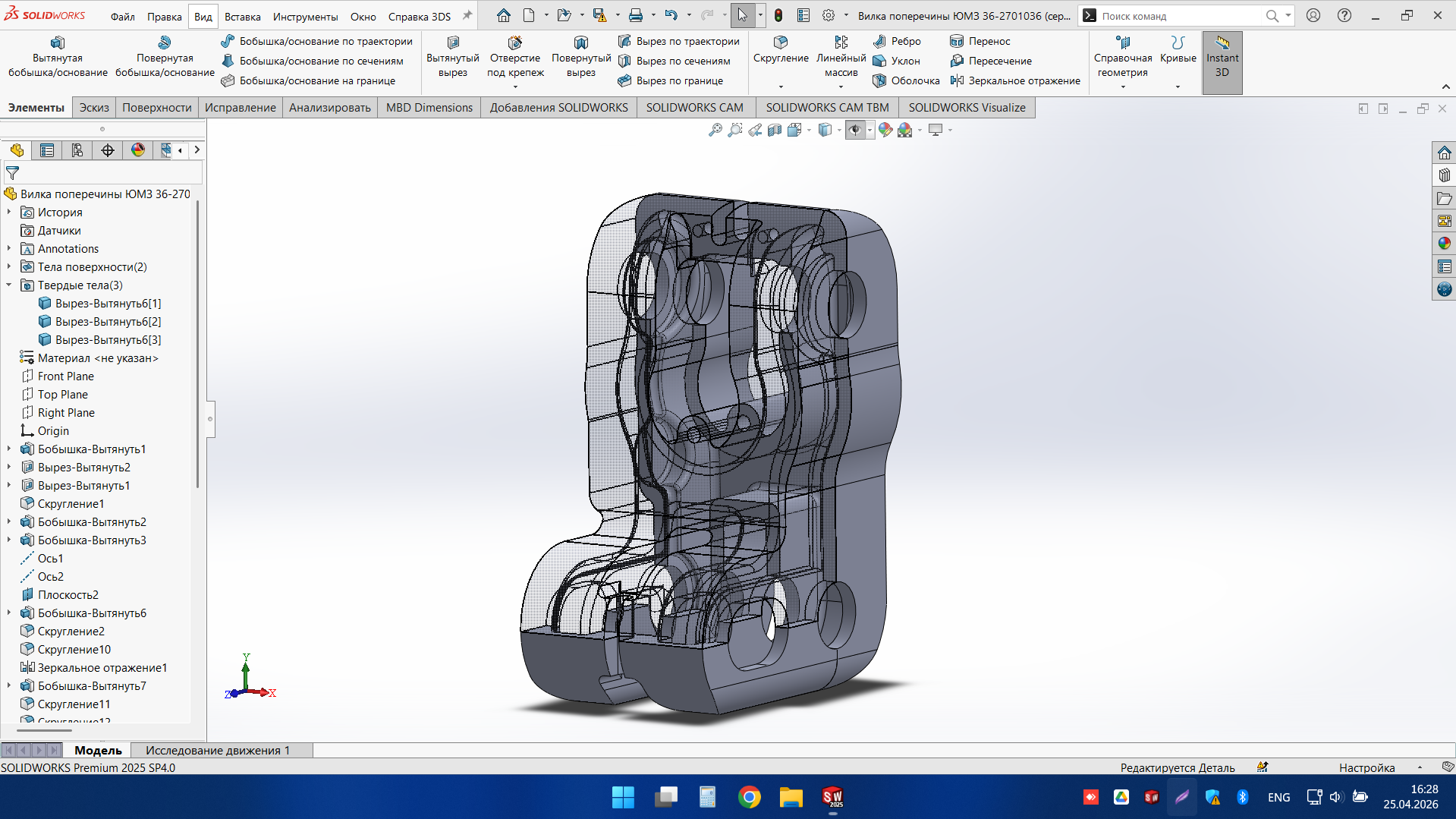
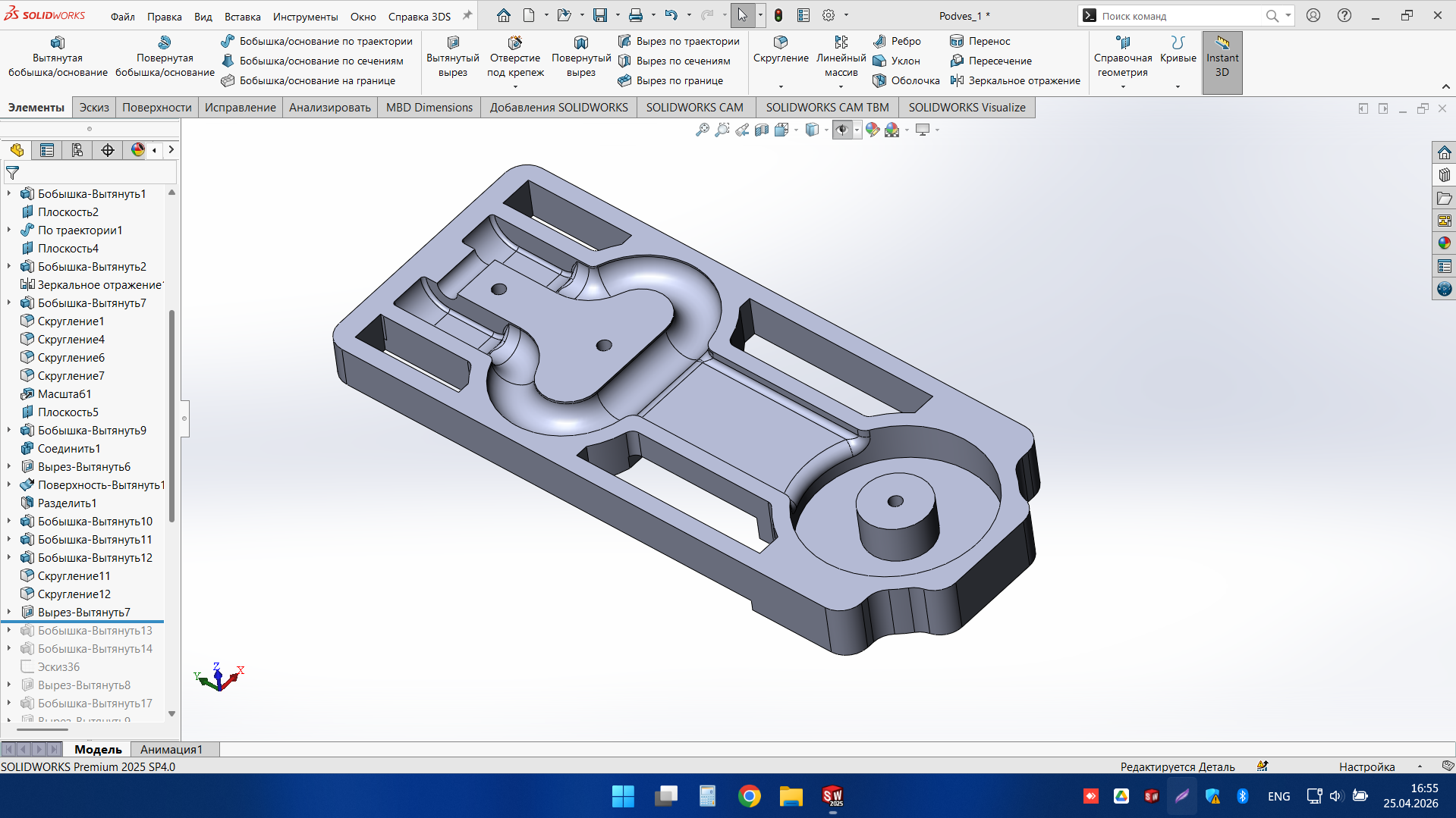
Cross-member fork
Compact mechanical housing with detailed internal geometry, fastening zones, and functional interface features. Developed as a clean and editable CAD model for further engineering, documentation, and technical coordination.
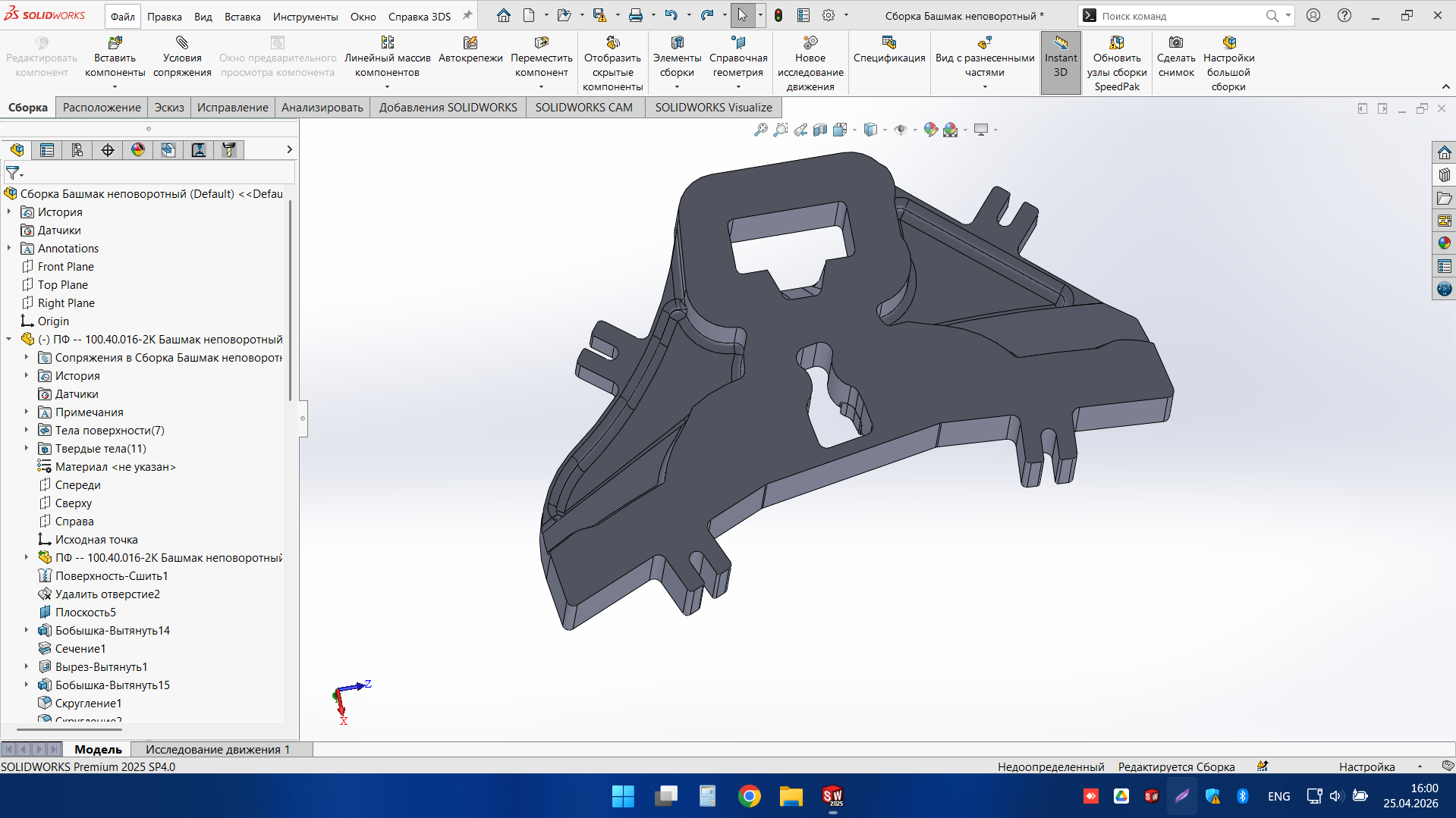
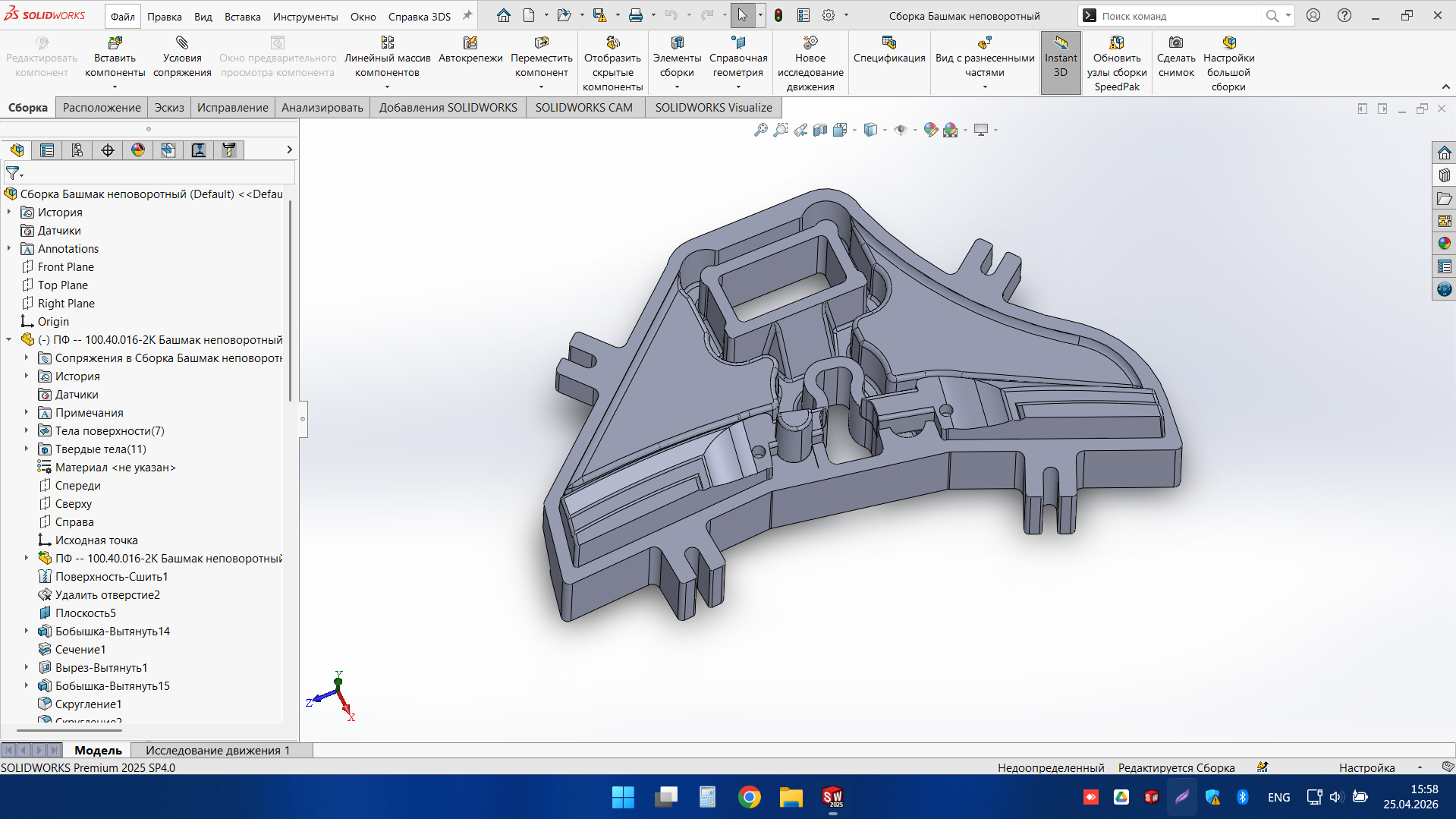
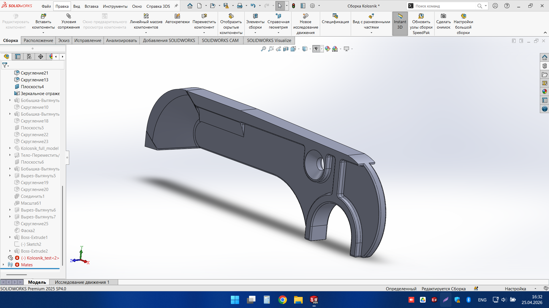
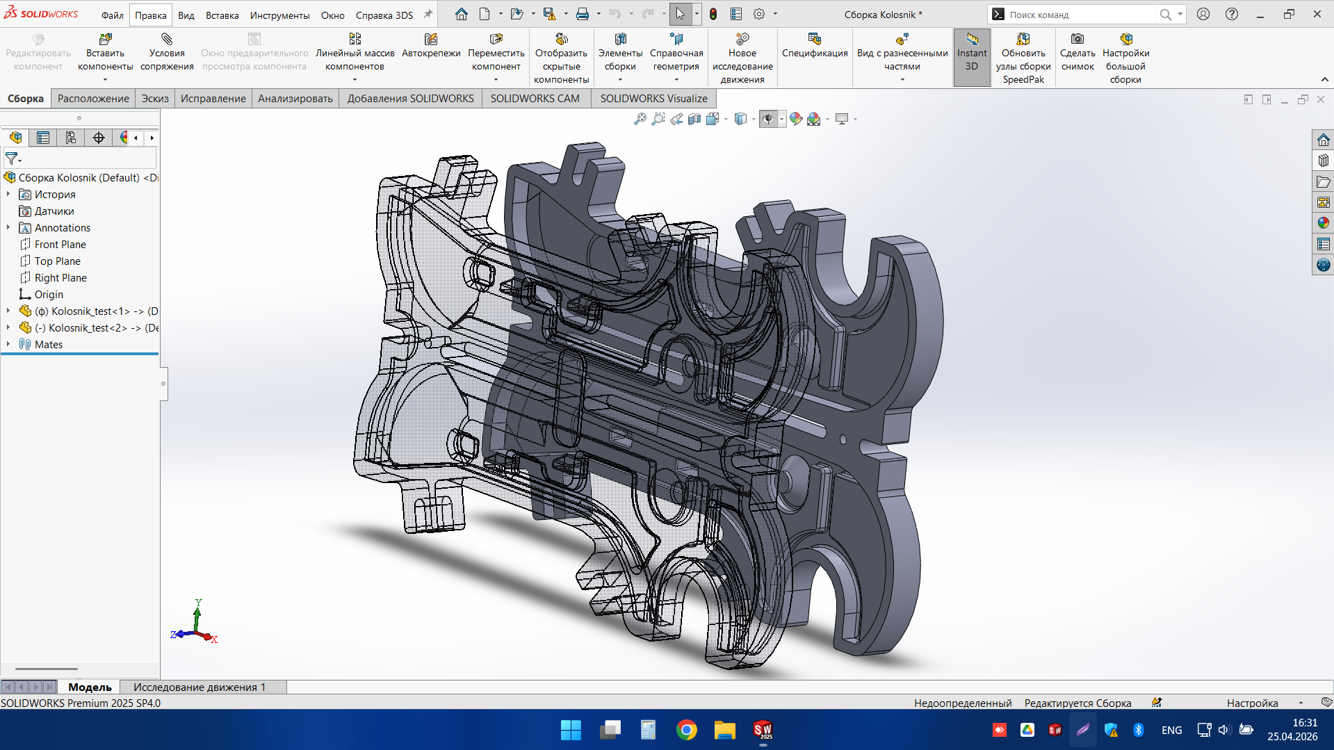
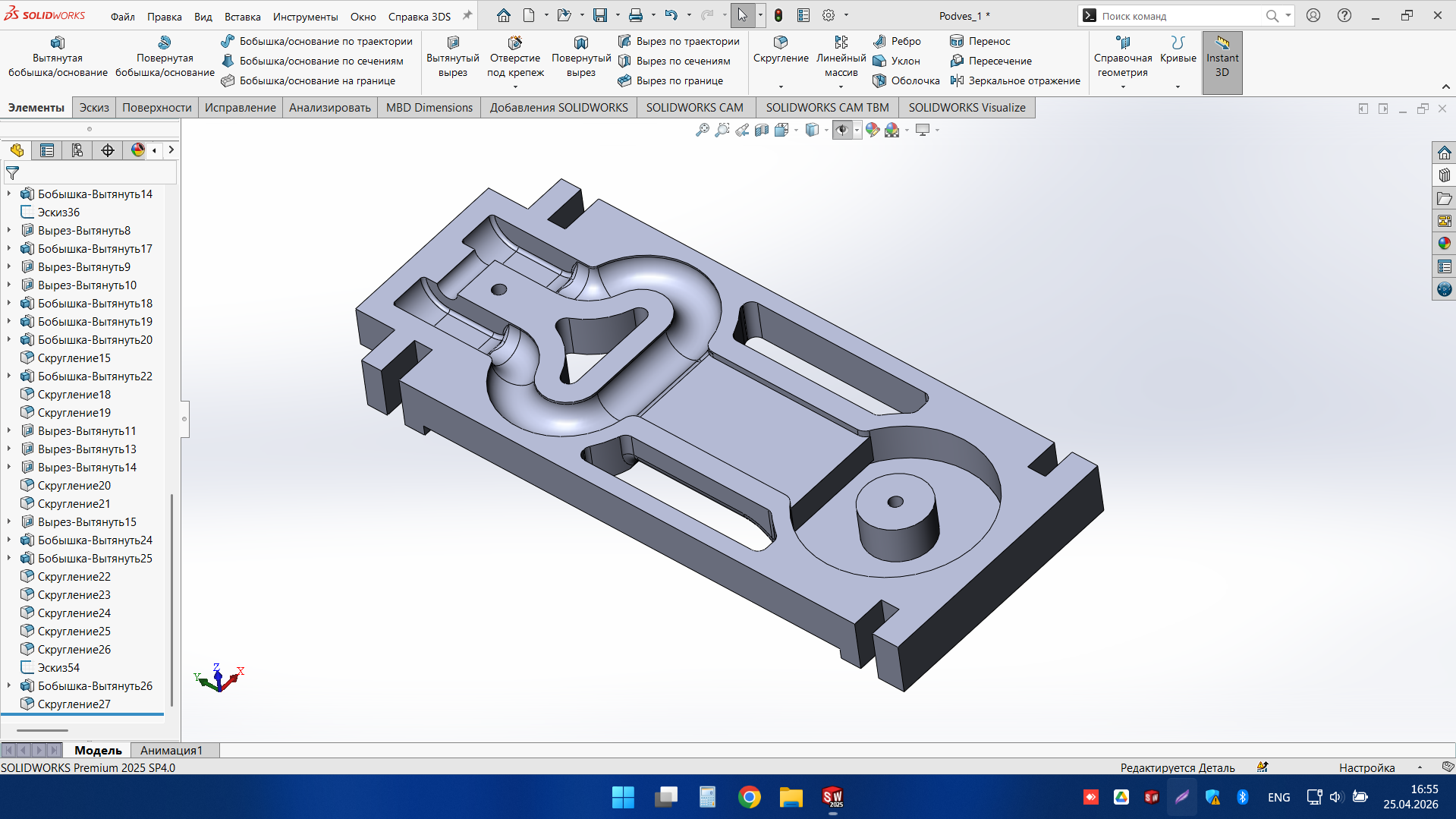
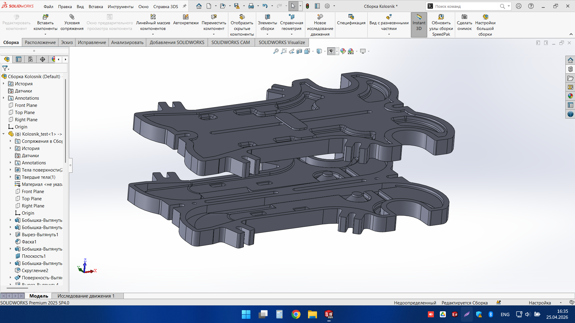
Symmetrical Structural Bracket Assembly
This project demonstrates our approach to detailed 3D CAD work for mirrored mechanical components that must fit together accurately in assembly. The model includes internal functional features, fastening zones, and precisely coordinated geometry across both halves of the part. The final result is a structured and editable CAD assembly ready for further design development and technical communication. It is a strong example of the engineering support we provide for industrial and mechanical projects.
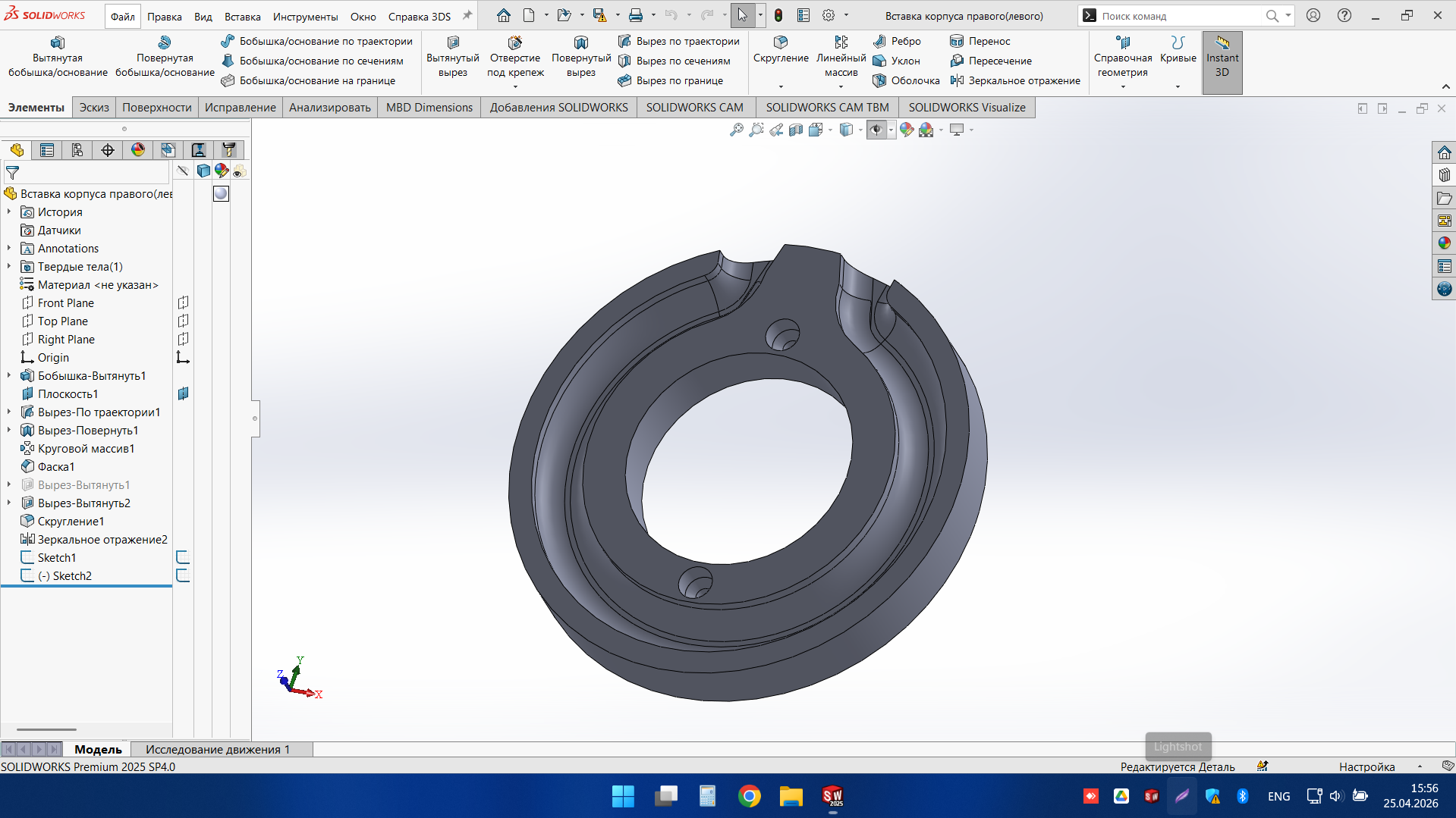
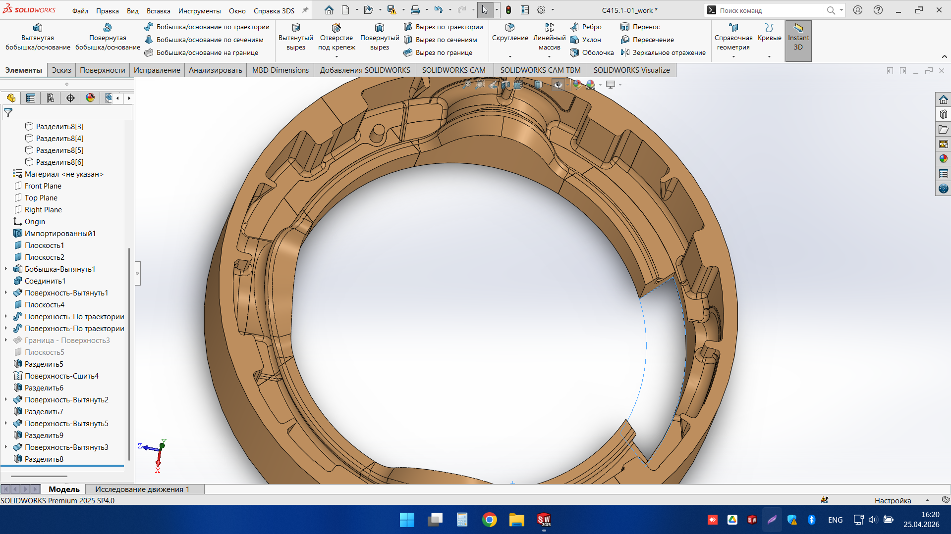
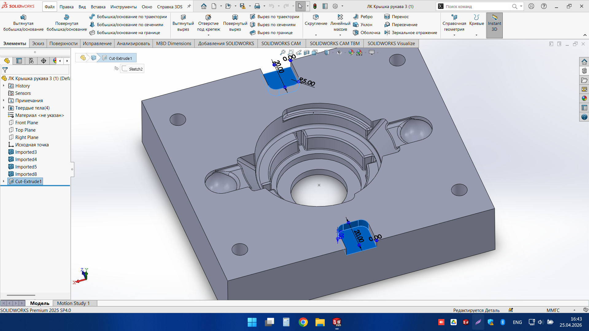
Precision Mounting Cover Plate
This part was developed as a precision mounting cover plate with a central functional opening, circular locating geometry, and multiple fastening points. The model includes accurately positioned cut-outs, interface grooves, and alignment features required for secure assembly and repeatable positioning. Special attention was given to the concentric internal geometry and the clean integration of mounting and guiding elements. The result is a structured and production-ready CAD model suitable for technical documentation, further design refinement, and manufacturing coordination.
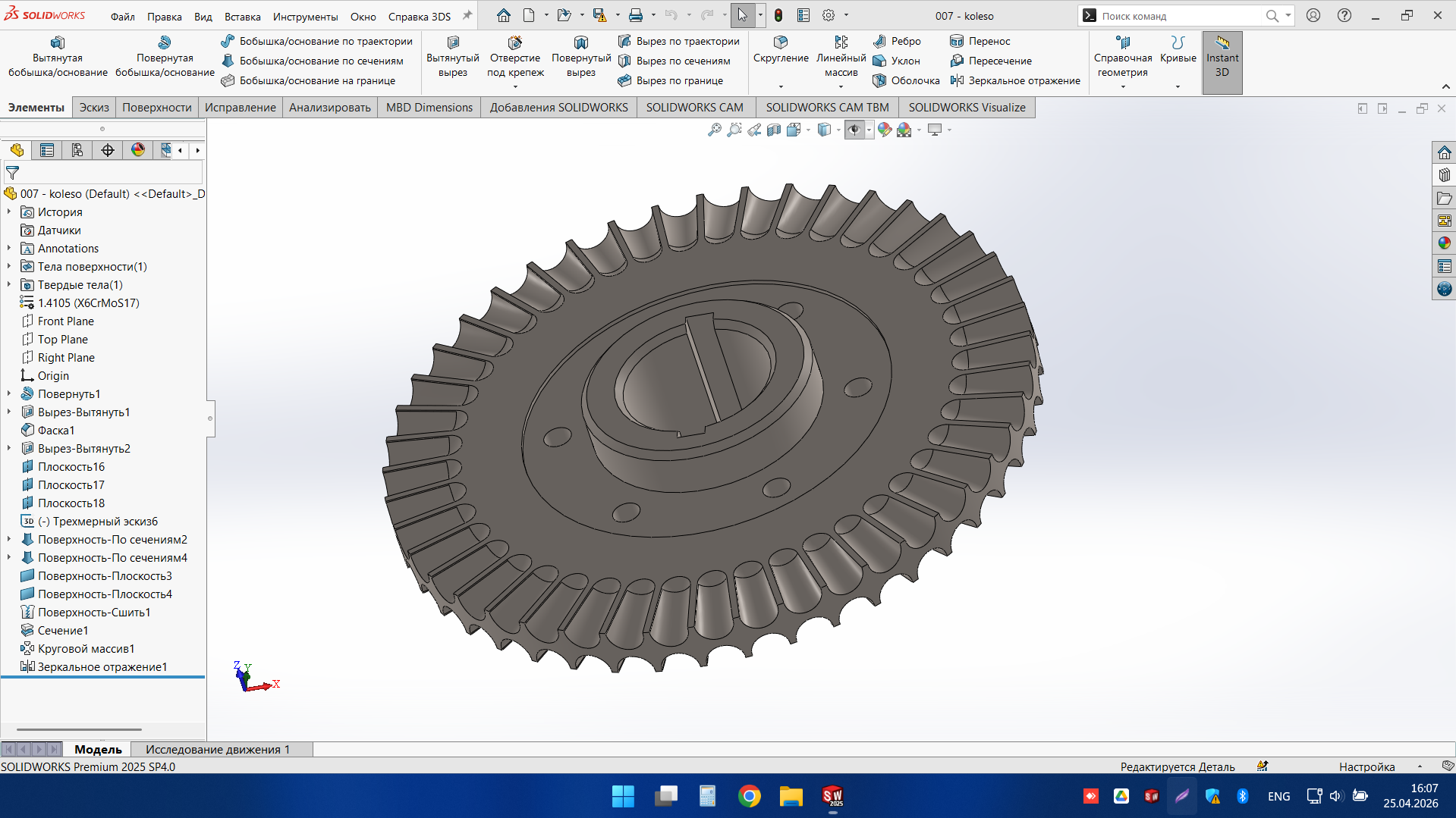
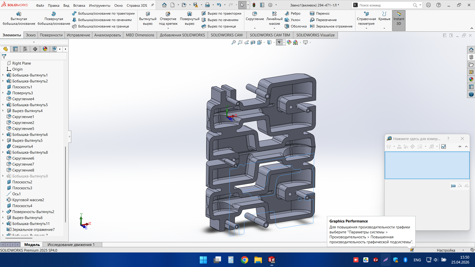
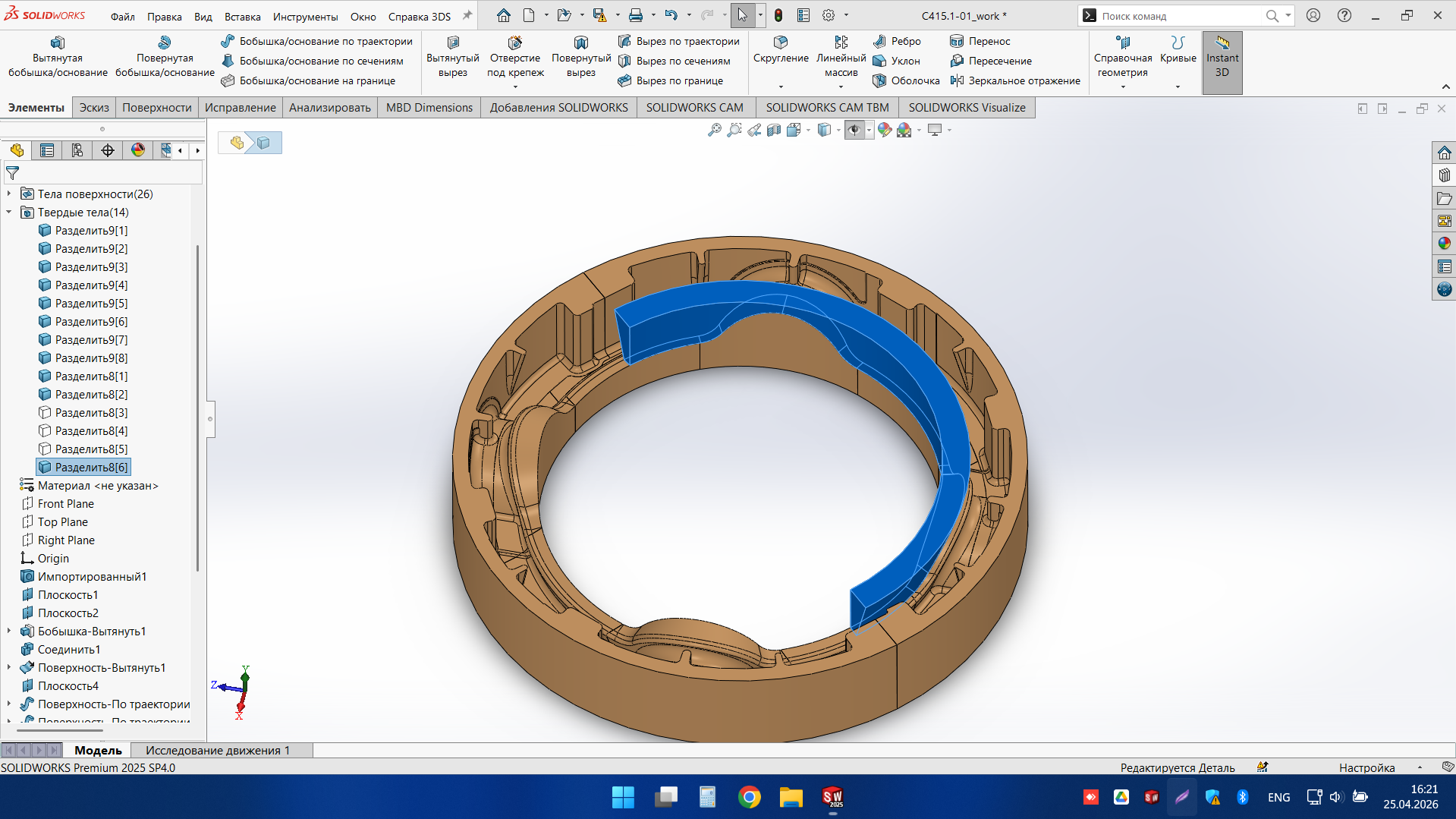
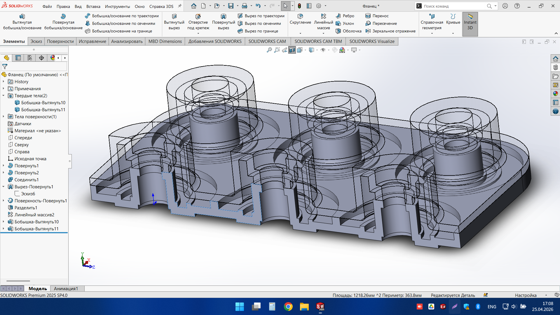
Multi-Cavity Flange Mould Insert
This project demonstrates our approach to CAD work for tooling components with repeated precision geometry and mould-related functional surfaces. The insert was developed as a clean and editable model with multiple identical forming positions, coordinated internal steps, and a structured cavity layout. The final result supports further tooling development, technical review, and manufacturing preparation. It is a strong example of the engineering support we provide for mould and production-related design projects.
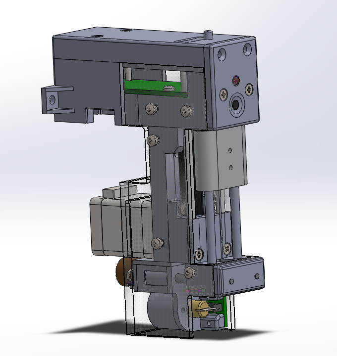
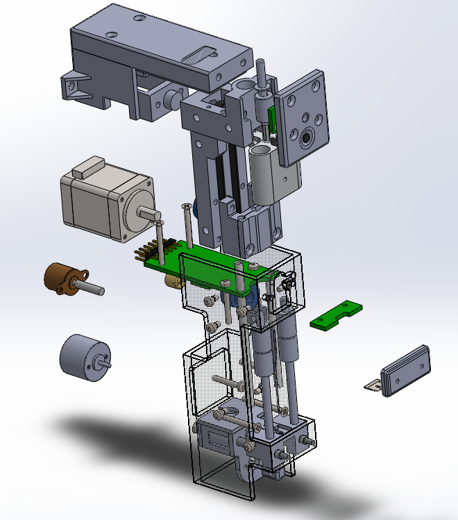
Compact Automated Feeding and Pressing Unit
The machine was developed as a detailed assembly with coordinated moving elements, drive components, mounting structures, and enclosure parts arranged in a compact and serviceable layout. The final model supports design review, engineering communication, and further refinement of the mechanism before production. It is a strong example of the digital engineering support we provide for custom machinery and automation-related projects